Altium Designer 板级标注-Board Level Annotation 使用教程
Written by: PNJie
2025/03/09
写在全面:
官方参考文档:板级标注 | Altium Designer 25 技术文档
Altium Designer中的标注功能(Annotation)可以对原理图进行批量标注,使用较多的功能是Annotate Schematics,但在遇到层次化设计原理图,一张原理图复用的情况下就需要用到板级标注(Board Level Annotate),检索发现中文社区对这一功能的分享几乎没有,因此笔者就自己的使用经验对此功能进行分享。
使用方法
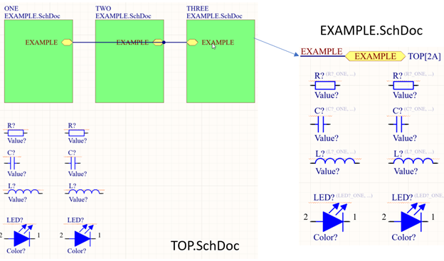
先说结论:对层次化设计原理图复用的标注步骤:(以如下工程为例:TOP为顶层原理图,顶层原理图中有元器件,EXAMPLE为子原理图,在TOP原理层中进行了三次复用):
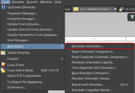
- Step 1:进行普通标注(Tools-Annotation-Annotate Schematics)
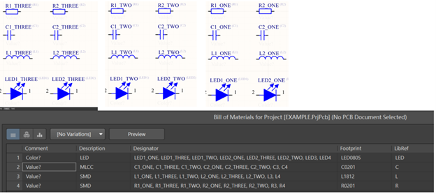
标注完成后子原理图的元器件标注为原理图标号_子原理图ROOM名称,如下图所示
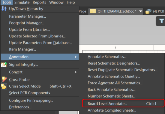
- Step 2:进行板级原理图标注(Board Level Annotate)
- Tool – Annotation – Board Level Annotate
-
ALL On
-
Annotate Options – Naming Scheme – 选择ComponentPrefixGlobalIndex
-
下方自行选择顺序和Order – OK – 关闭此面板
-
Annotate – Annotate Undesigned(只有此选项可选)
-
Accept Changes – Validate Changes – Execute Changes
-
标注完成
至此层次设计复用原理图标注完成,进行到这一步可能会发现TOP原理图中的元器件也同时拥有两个标号,原因是Editor中的标号为Logical 标号,实际Physical 标号与Logical标号不重复。因此Board level十分适用于原理图标号无法修改,但却需要复用调用原理图的使用场景。生成BOM会按照Physical 标号生成。
“`如果不进行step 1直接 使用board level annotate ?
Q:如果不进行step 1直接 使用board level annotate ?
<pre><code class="line-numbers">则标注会变为R?1 R?2,此时validate Schematic 不会有Duplicate 报错,只会有Undesigned part警告
“`Step 1和step 2步骤进行顺序调换?
Q:Step 1和step 2步骤进行顺序调换?
则会发现元器件的Logical name变正常了,但Physical name依旧是R?1 R?2,强迫症会非常难受
板级标注的一些定义
Board Level Annotation
Board Level Annotation provides a mapping between designators used in the Schematic (LogicalDesign and their real world counterparts on the PCB (Physical) Design. While Board LevelAnnotation can be used in any desian, it is especially useful for multi-channel desians and / ordesians that incorporate Device Sheets where the desianators cannot be edited on the DeviceSheet itself. In this way, the entire design can be re-annotated without actually modifying theoriginal Device Sheet(s).
Board Level Annotation resolves any conflicting annotation problems that may occur due toduplicate designators across a project and stores its changes in a *.Annotation text file. itincludes additional keywords for customizing naming schemes and allows them to be applied toall or only a select range of parts.
In summary, use Board Level Annotation to:
Annotate the compiled components in Device Sheets
Uniquely name all components across several channels using naming schemes whichinclude positional annotation, global indexing, and other configurable options